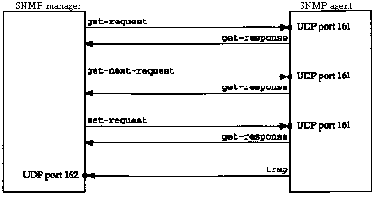
Figure 25.1 Summary of the five SNMP operators.
As the number of networks within an organization grows, along with the diversity of systems comprising this internet (routers from various vendors, hosts with embedded router functionality, terminal servers, etc.), managing all these systems within a coherent framework becomes important. This chapter looks at the standards used within the Internet protocol suite for network management.
Network management of a TCP/IP internet consists of network management stations (managers) communicating with network elements. The network elements can be anything that runs the TCP/IP protocol suite: hosts, routers, X terminals, terminal servers, printers, and so on. The software in the network element that runs the management software is called the agent. Management stations are normally workstations with color monitors that graphically display relevant facts about the elements being monitored (which links are up and down, volume of traffic across various links over time, etc.).
"The communication can be two way: the manager asking the agent for a specific value ("how many ICMP port unreachables have you generated?"), or the agent telling the manager that something important happened ("an attached interface has gone down"). Also, the manager should be able to set variables in the agent ("change the value of the default IP TTL to 64"), in addition to reading variables from the agent. TCP/IP network management consists of three pieces.
These RFCs define what is now called SNMPv1, or just SNMP, which is the topic of this chapter. During 1993 additional RFCs were published specifying SNMP Version 2 (SNMPv2), which we describe in Section 25.12.
Our approach to SNMP in this chapter is to describe
the protocol between the manager and the agent first, and then
look at the data types for the variables maintained by the agent.
We describe the database of information maintained by the agent
(the MIB), looking at the groups that we've described in this
text: IP, UDP, TCP, and so on. We show examples at each point
along the way, tying network management back to the protocol concepts
from earlier chapters.
25.2 Protocol
SNMP defines only five types of messages that are exchanged between the manager and agent.
The first three messages are sent from the manager to the agent, and the last two are from the agent to the manager. (We'll refer to the first three as the get, get-next, and set operators.) Figure 25.1 summarizes these five operators.
Since four of the five SNMP messages are simple request-reply protocols (the manager sends a request, the agent sends back a reply) SNMP uses UDP. This means that a request from the manager may not arrive at the agent, and the agent's reply may not make it back to the manager. The manager probably wants to implement a timeout and retransmission.
The manager sends its three requests to UDP port 161. The agent sends traps to UDP port 162. By using two different port numbers, a single system can easily run both a manager and an agent. (See Exercise 25.1.)
Figure 25.2 shows the format of the five SNMP messages, encapsulated in a UDP datagram.
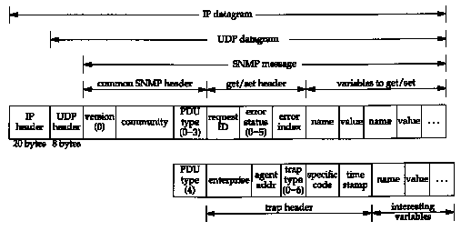
In this figure we specify the size in bytes of the IP and UDP headers only. This is because the encoding used for the SNMP message-called ASN.1 and BER, which we describe later in this chapter-varies depending on the type of variable and its value.
The version is 0. This value is really the version number minus one, as the version of SNMP that we describe is called SNMPv1.
Figure 25.3 shows the values for the PDU type. (PDU stands for Protocol Data Unit, a fancy word for "packet.")
| Name | |
| get-request | |
| get-next-request | |
| set-request | |
| get-response | |
| trap |
The community is a character string that is a cleartext password between the manager and agent. A common value is the 6-character string public.
For the get, get-next, and set operators, the request ID is set by the manager, and returned by the agent in the get-response message. We've seen this type of variable with other UDP applications. (Recall the DNS identification field in Figure 14.3, and the transaction ID field in Figure 16.2.) It lets the client (the manager in this case) match the responses from the server (the agent) to the queries that the client issued. "This field also allows the manager to issue multiple requests to one or more agents, and then be able to sort out the returned replies.
The error status is an integer returned by the agent specifying an error. Figure 25.4 shows the values, names, and descriptions.
| noError | all is OK | |
| tooBig | agent could not fit reply into a single SNMP message | |
| noSuchName | operation specified a nonexistent variable | |
| badValue | a set operation specified an invalid value or syntax | |
| readonly | manager tried to modify a read-only variable | |
| genErr | some other error |
If an error occurred, the error index is an integer offset specifying which variable was in error. It is set by the agent only for the noSuchName, badValue, and readonly errors.
A list of variable names and values follows in the get, get-next, and set requests. The value portion is ignored for the get and get-next operators.
For the trap operator
(a PDU type of 4), the format of the SNMP message changes.
We describe the fields in the trap header when we describe this
operator in Section 25.10.
25.3 Structure of Management Information
SNMP uses only a few different types of data. In this section we'll look at those data types, without worrying about how the data is actually encoded (that is, the bit pattern used to store the data).
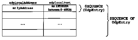
For example, the UDP listener table is named udpTable and it is a SEQUENCE OF the 2-element SEQUENCE (structure) UdpEntry that we just described. Figure 25.5 shows this two-dimensional array.
The number of rows in these tables is not specified
by SNMP, but we'll see that a manager using the get-next
operator (Section 25.7) can determine when the final row of a
table has been returned. Also, in Section 25.6 we'll see how the
manager specifies which row of a table it wants to get or set.
25.4 Object Identifiers
An object identifier is a data type specifying an authoritatively named object. By "authoritative" we mean that these identifiers are not assigned randomly, but are allocated by some organization that has responsibility for a group of identifiers.
An object identifier is a sequence of integers separated by decimal points. These integers traverse a tree structure, similar to the DNS (Figure 14.1) or a Unix filesystem. There is an unnamed root at the top of the tree where the object identifiers start. (This is the same direction of tree traversal that's used with a Unix filesystem.)
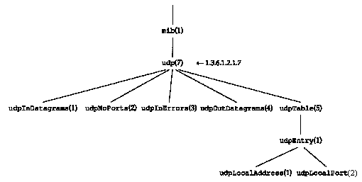
Figure 25.6 shows the structure of this tree when used with SNMP. All variables in the MIB start with the object identifier 1.3.6.1.2.1.
Each node in the tree is also given a textual name. The name corresponding to the object identifier 1.3.6.1.2.1 is iso.org.dod.internet.mgmt.mib. These names are for human readability. The names of the MIB variables that are in the packets exchanged between the manager and agent (Figure 25.2) are the numeric object identifiers, all of which begin with 1.3.6.1.2.1.
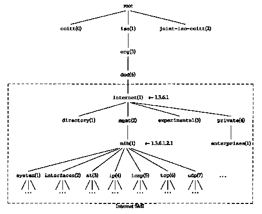
Besides the mib object
identifiers in Figure 25.6 we also show one named iso.org.dod.internet.private.enterprises
(1.3.6.1.4.1). "This is where vendor-specific MIBs are located.
The Assigned Numbers RFC lists around 400 identifiers registered
below this node.
25.5 Introduction to the Management Information Base
The Management Information Base, or MIB, is the database of information maintained by the agent that the manager can query or set. We describe what's called MIB-II, specified in RFC 1213 [McCloghrie and Rose 1991].
As shown in Figure 25.6, the MIB is divided into groups named system, interfaces, at (address translation), ip, and so on.
In this section we describe only the variables in the UDP group. This is a simple group with only a few variables and a single table. In the next sections we use this group to show the details of instance identification, lexicographic ordering, and some simple examples of these features. After these examples we return to the MIB in Section 25.8 and describe some of the other groups in the MIB.
In Figure 25.6 we showed the group named udp beneath mib. Figure 25.7 shows the structure of the UDP group.
There are four simple variables and a table containing two simple variables. Figure 25.8 describes the four simple variables.
| udpInDatagrams | Counter | Number of UDP datagrams delivered to user processes. | |
| udpNoPorts | Counter | Number of received UDP datagrams for which no application process was at the destination port. | |
| udpInErrors | Counter | Number of undeliverable UDP datagrams for reasons other than no application at destination port (e.g., UDP checksum error). | |
| udpOutDatagrams | Counter | Number of UDP datagrams sent. |
We'll use this format to describe all the MIB variables in this chapter. The column labeled "R/W" is empty if the variable is read-only, or contains a bullet (*) if the variable is read-write. We always include this column, even if all the variables in a group are read-only (since they are in the udp group) to reiterate that none of the variables can be set by the manager. Also, when the data type is an INTEGER with bounds, we specify the lower limit and upper limit, as we do for the UDP port number in the next figure.
Figure 25.9 describes the two simple variables in the udpTable.
|
| |||
| udpLocalAddress | lpAddress | Local IP address for this listener. 0.0.0.0 indicates the listener is willing to receive datagrams on any interface. | |
| udpLocalPort | [0..65535] | Local port number for this listener. | |
Each time we describe the variables in an SNMP table, the first row of the figure indicates the value of the "index" used to reference each row of the table. We show some examples of this in the next section.
There is a relationship between the first three counters in Figure 25.8. Case Diagrams [Case and Partridge 1989] visually illustrate the relationships between the various MIB variables in a given group. Figure 25.10 is a Case Diagram for the UDP group.
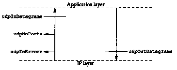
What this diagram shows is that the number of UDP datagrams delivered to applications (udpInDatagrams) is the number of UDP datagrams delivered from IP to UDP, minus udpInErrors, minus udpNoPorts. Also, the number of UDP datagrams delivered to IP (udpOutDatagrams) is the number passed to UDP from the applications. This illustrates that udpInDatagrams does not include udpInErrors or udpNoPorts.
These diagrams were used during the development of
the MIB to verify that all data paths for a packet were accounted
for. [Rose 1994] shows Case Diagrams for all the groups in the
MIB.
25.6 Instance Identification
Every variable in the MIB must be identified when SNMP is referencing it, to fetch or set its value. First, only leaf nodes are referenced. SNMP does not manipulate entire rows or columns of tables. Returning to Figure 25.7, the leaf nodes are the four that we described in Figure 25.8 and the two in Figure 25.9. mib, udp, udpTabie, and udpEntry are not leaf nodes.
Simple variables are referenced by appending ".0" to the variable's object identifier. For example, the counter udpInDatagrams from Figure 25.8, whose object identifier is 1.3.6.1.2.1.7.1, is referenced as 1.3.6.1.2.1.7.1.0. The textual name of this reference is iso.org.dod.internet.mgmt.mib.udp.udpInDatagrams.0.
Although references to this variable are normally abbreviated as just udpInDatagrams.0, we reiterate that the name of the variable that appears in the SNMP message (Figure 25.2) is the object identifier 1.3.6.1.2.1.7.1.0.
Instance identification of table entries is more detailed. Let's return to the UDP listener table (Figure 25.7).
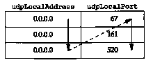
One or more indexes are specified in the MIB for each table. For the UDP listener table, the MIB defines the index as the combination of the two variables udpLocalAddress, which is an IP address, and udpLocalPort, which is an integer. (We showed this index in the top row in Figure 25.9.)
Assume there are three rows in the UDP listener table: the first row is for IP address 0.0.0.0 and port 67, the second for 0.0.0.0 and port 161, and the third for 0.0.0.0 and port 520. Figure 25.11 shows this table.
This implies that the system is willing to receive UDP datagrams on any interface for ports 67 (BOOTP server), 161 (SNMP), and 520 (RIP). The three rows in the table are referenced as shown in Figure 25.12.
There is an implied ordering in the MIB based on the order of the object identifiers. All the entries in MIB tables are lexicographically ordered by their object identifiers. This means the six variables in Figure 25.12 are ordered in the MIB as shown in Figure 25.13. Two key points result from this lexicographic ordering.
| 1.3.6.1.2.1.7.5.1.1.0.0.0.0.67 1.3.6.1.2.1.7.5.1.2.0.0.0.0.67 | udpLocalAddress.0.0.0.0.67 udpLocalPort.0.0.0.0.67 | 67 | |
| 1.3.6.1.2.1.7.5.1.1.0.0.0.0.161 1.3.6.1.2.1.7.5.1.2.0.0.0.0.161 | udpLocalAddress.0.0.0.0.161 udpLocalPort.0.0.0.0.161 | 161 | |
| 1.3.6.1.2.1.7.5.1.1.0.0.0.0.520 1.3.6.1.2.1.7.5.1.2.0.0.0.0.520 | udpLocalAddress.0.0.0.0.520 udpLocalPort.0.0.0.0.520 | 520 |
(lexicographically ordered) | |||
| 1.3.6.1.2.1.7.5.1.1.0.0.0.0.67
1.3.6.1.2.1.7.5.1.1.0.0.0.0.161 1.3.6.1.2.1.7.5.1.1.0.0.0.0.520 | udpLocalAddress.0.0.0.0.67 udpLocalAddress.0.0.0.0.161 udpLocalAddress.0.0.0.0.520 | 0.0.0.0 0.0.0.0 | |
| 1.3.6.1.2.1.7.5.1.2.0.0.0.0.67
1.3.6.1.2.1.7.5.1.2.0.0.0.0.161 1.3.6.1.2.1.7.5.1.2.0.0.0.0.520 | udpLocalPort.0.0.0.0.67 udpLocalPort.0.0.0.0.161 udpLocalPort.0.0.0.0.520 | 161 520 |
Figure 25.14 shows this column-row order for our sample UDP listener table.
We'll also see this column-row ordering when we use
the get-next operator in the next section.
25.7 Simple Examples
In this section we'll show some examples that fetch the values of variables from an SNMP agent. The software used to query the agent is called snmpi and is from the ISODE system. Both are described briefly in [Rose 1994].
We'll query a router for two simple variables from the UDP group:
sun % snmpi -a gateway -c secret
snmpi> get udpInDatagrams.0
udpNoPorta.0
udplnDatagrams.0=616168
udpNoPorts.0=33
snmpi> quit
The -a option identifies the agent we want to communicate with, and the -c option specifies the SNMP community. It is a password supplied by the client (snmpi in this case) and if the server (the agent in the system gateway) recognizes the community name, it honors the manager's request. An agent could allow clients within one community read-only access to its variables, and clients in another community read-write access.
The program outputs its snmpi> prompt, and we can type commands such as get, which translates into an SNMP get-request message. When we're done, we type quit. (In all further examples we'll remove this final quit command.) Figure 25.15 shows the two lines of tcpdump output for this example.
| 1 | 0.0 | sun.1024 > gateway.161: GetRequest(42)
1.3.6.1.2.1.7.1.0 1.3.6.1.2.1.7.2.0 |
| 2 | 0.348875 (0.3489) | gateway.161 > sun.1024: GetResponse(46) 1.3.6.1.2.1.7.1.0=616168 1.3.6.1.2.1.7.2.0=33 |
The request for the two variables is sent in a single UDP datagram, and the response is also a single UDP datagram.
We show the variables as their respective object identifiers, because that is what's sent in the SNMP messages. We had to specify the instance of the two variables as 0. Notice also that the name of the variable (its object identifier) is always returned in the response. We'll see below that this is required for the get-next operator to work.
The operation of the get-next operator is based on the lexicographic ordering of the MIB. We start the following example by asking for the next object identifier after udp (without specifying any instance, since this is not a leaf object). This returns the first object in the UDP group. We then ask for the next entry after this one, and the second entry is returned. We repeat this one more time to get the third entry:
sun % sninpi -a gateway -c secret
snmpi> next udp
udpInDatagrams.0=616318
snmpi> next udpInDatagraros.0
udpNoPorts.0=33
snmpi> next udpNoPorts.0
udpInErrors.0=0
This example shows why a get-next operator must return the name of the variable: we ask the agent for the next variable, and the agent returns its name and value.
Using the get-next operator in this fashion, one could imagine a manager with a loop that starts at the beginning of the MIB and queries the agent for every variable that the agent maintains. Another use of this operator is to iterate through tables.
We can reiterate the column-row ordering of tables using our simple query program to step through the entire UDP listener table. We start by asking for the next variable after udpTable. Since this is not a leaf object we can't specify an instance, but the get-next operator still returns the next object in the table. We then work our way through the table, with the agent returning the next variable, in column-row order:
sun % snmpi-a gateway -c secret
snmpi> next udpTable
udpLocalAddress.0.0.0.0.67=0.0.0.0
snmpi> next udpLocalAddress.0.0.0.0.67
udpLocalAddress.0.0.0.0.161-0.0.0.0
snmpi> next udpLocalAddress.0.0.0.0.161
udpLocalAddress.0.0.0.0.52 0=0.0.0.0
snmpi> next udpLocalAddress.0.0.0.0.520
udpLocalPort.0.0.0.0.67=67
snmpi> next udpLocalPort.0.0.0.0.67
udpLocalPort.0.0.0.0.161=161
snmpi> next udpLocalPort.0.0.0.0.161
udpLocalPort.0.0.0.0.520=520
snmpi> next udpLocalPort.0.0.0.0.520
snmpInPkts.0=59 we're finished
with the UDP listener table
We see that the order returned corresponds to Figure 25.14.
How does a manager know when it reaches the end of
a table? Since the response to the get-next
operator contains the name of the next entry in the MIB after
the table, the manager can tell when the name changes. In our
example the last entry in the UDP listener table is followed by
the variable snmpInPkts.
25.8 Management Information Base (Continued)
We now return to the description of the MIB. We describe only the following groups: system (system identification), if (interfaces) , at (address translation), ip, icmp, and tcp. Additional groups are defined.
The system group is simple; it consists of seven simple variables (i.e., no tables). Figure 25.16 shows their names, data types, and descriptions.
| sysDescr | Display String | Textual description of entity. | |
| sysObjectID | ObjectID | Vendor's ID within the subtree 1.3.6.1.4.1. | |
| sysUpTime | TimeTicks | Time in hundredths of a second since network management portion of system was rebooted. | |
| sysContact | DisplayString | * | Name of contact person and how to contact them. |
| sysName | DisplayString | * | Node's fully qualified domain name (FQDN). |
| sysLocation | DisplayString | * | Physical location of node. |
| sysServices | [0..127] | Value indicating services provided by node. It is the sum of the layers in the OSI model supported by the node. The following values are added together, depending on the services provided: 0x01 (physical) , 0x02 (datalink), 0x04 (internet), 0x08 (end-to-end), 0x40 (application). |
We can query the router netb for some of these variables:
sun % snmpi -a netb -c secret
snmpi> get sysDescr.0 sysObjectID.0 sysDpTime.0
sysServices.0
sysDescr.0="Epilogue Technology SNMP agent for Telebit
NetBlazer"
sysObjectID.0=1.3.6.1.4.1.12.42.3.1
sysUpTime.0=22 days, 11 hours, 23 minutes, 2 seconds (194178200
timeticks)
sysServices.0=0xc<internet,transport>
The system's object identifier is in the internet.private.enterprises group (1.3.6.1.4.1) from Figure 25.6. From the Assigned Numbers RFC we can determine that the next object identifier (12) is assigned to the vendor (Epilogue).
We can also see that the sysServices variable is the sum of 4 and 8: this element supports the Internet layer (i.e., routing) and the transport layer (i.e., end-to-end).
Only one simple variable is defined for this group: the number of interfaces on the system, shown in Figure 25.17.
| ifNumber | INTEGER | Number of network interfaces on system. |
This group also defines a table with 22 columns. Each row of the table defines the characteristics for each interface, as shown in Figure 25.18.
| ifIndex | INTEGER | Index of interface, between one and if Number. | |
| ifDescr | DisplayString | Textual description of interface. | |
| ifType | INTEGER | Type, for example: 6 = Ethernet, 7 = 802.3 Ethernet, 9 = 802.5 token ring, 23 = PPP, 28 = SLIP, and many other values. | |
| ifMtu | INTEGER | MTU of interface. | |
| ifSpeed | Gauge | Speed in bits/sec. | |
| ifPhysAddress | PhysAddress | Physical address, or string of 0 length for interfaces without physical addresses (e.g., serial links). | |
| ifAdminStatus | [1..3] | Desired state of interface: 1 = up, 2 = down, 3 = testing. | |
| ifOperStatus | [1..3] | Current state of interface: 1 = up, 2 = down, 3 = testing. | |
| ifLastChange | TimeTicks | Value of sysUpTime when interface entered current operational state. | |
| ifInoctets | Counter | Total number of bytes received, including framing characters. | |
| ifInUcastPkts | Counter | Number of unicast packets delivered to higher layers. | |
| ifInNUcastPkts | Counter | Number of nonunicast (i.e., broadcast or multicast) packets delivered to higher layers. | |
| ifInDiscards | Counter | Number of received packets discarded even though no error in packet (i.e., out of buffers). | |
| ifInErrors | Counter | Number of received packets discarded because of errors. | |
| ifInUnknownProtos | Counter | Number of received packets discarded because of unknown protocol. | |
| ifOutoctets | Counter | Number of bytes transmitted, including framing characters. | |
| ifOutUcastPkts | Counter | Number of unicast packets received from higher layers. | |
| ifOutNUcastPkts | Counter | Number of nonunicast (i.e., broadcast or multicast) packets received from higher layers. | |
| ifOutDiscards | Counter | Number of outbound packets discarded even though no error in packet (i.e., out of buffers). | |
| ifOutErrors | Counter | Number of outbound packets discarded because of errors. | |
| ifOutQLen | Gauge | Number of packets in output queue. | |
| ifSpecific | ObjectID | A reference to MIB definitions specific to this particular type of media. | |
We can query the host sun for some of these variables for all its interfaces. Wet expect to find three interfaces, as in Section 3.8, if the SLIP interface is up:
sun % snmpi -a sun
snropi> next ifTable
first see what index of first
interface is
if Index.1=1
snmpi> get ifDescr.1 if Type.1 ifMtu.1 if Speed.1 ifPhysAddress.1
ifDescr.1="le0"
if Type.1=ethernet-csmacd(6)
ifMtu.1=1500
ifSpeed, 1=10000000
ifPhysAddress.1=0x08:00:20;03:f6:42
snmpi> next ifDescr.1 if Type.1 ifMtu.1 if Speed.1 ifPhysAddress.1
ifDescr.2="sl0"
ifType.2=propPointToPointSerial(22)
ifMtu.2=552
ifSpeed.2=0
ifPhysAddress.2=0x00:00:00:00:00:00
snmpi> next ifDescr.2 ifType.2 ifMtu.2 if Speed.2 ifPhysAddress.2
ifDescr.3="lo0"
ifType.3=softwareLoopback(24)
ifMtu.3=1536
ifSpeed.3=0
ifPhysAddress.3=0x00:00:00:00:00:00
We first get five variables for the first interface using the get operator, and then get the same five variables for the second interface using the get-next operator. The last command gets these same five variables for the third interface, again using the get-next command.
The interface type for the SLIP link is reported as proprietary point-to-point serial, not SLIP. Also, the speed of the SLIP link is not reported.
It is critical to understand the relationship between the get-next operator and the column-row ordering. When we say next ifDescr.1 it returns the next row of the table for this variable, not the next variable in the same row. If tables were stored in a row-column order instead, we wouldn't be able to step to the next occurrence of a given variable this way.
The address translation group is mandatory for all systems, but was deprecated by MIB-II. Starting with MIB-II, each network protocol group (e.g., IP) contains its own address translation tables. For IP it is the ipNetToMediaTable.
Only a single table with three columns is defined for the at group, shown in Figure 25.19.
We can use a new command within the snmpi program to dump an entire table. We'll query the router named kinetics (which routes between a TCP/IP network and an AppleTalk network) for its entire ARP cache. This output reiterates the lexicographic ordering of the entries in the table:
| Address translation table, index = < atIflndex >.1.< atNetAddress > | |||
| atiflndex | INTEGER | Interface number: ifIndex. | |
| atPhysAddress | PhysAddress | Physical address. Setting this to a string of 0 length invalidates the entry. | |
| atNetAddress | NetworkAddress | IP address. | |
sun % snmpi -a kinetics -c secret dump at
atiflndex.1.1.140.252.1.4=1
atiflndex.1.1.140.252.1.22=1
atiflndex.1.1.140.252.1.183=1
atiflndex.2.1.140.252.6.4=2
atiflndex.2.1.140.252.6.6=2
atPhysAddress.1.1.140.252.1.4=0xaa:00:04:00:f4:14
atPhysAddress.1.1.140.252.1.22=0x08:00:20:0f:2d:38
atPhysAddress.1.1.140.252.1.183=0x00:80:ad:03:6a:80
atPhysAddress.2.1.140.252.6.4=0x00:02:16:48
atPhysAddress.2.1.140.252.6.6=0x00:02:3c:48
atNetAddress.1.1.140.252.1.4=140.252.1.4
atNetAddress.1.1.140.252.1.22=140.252.1.22
atNetAddress.1.1.140.252.1.183=140.252.1.183
atNetAddress.2.1.140.252.6.4=140.252.6.4
atNetAddress.2.1.140.252.6.6=140.252.6.6
If we watch the packet exchange using tcpdump, when snmpi dumps an entire table it first issues a get-next for the table name (at in this example) to get the first entry. It prints the first entry and issues another get-next. This continues until the entire table has been dumped.
Figure 25.20 shows the arrangement of this table.
| atIflndex | atPhysAddress | atNetAddress |
| 0xaa:00:04:00:f4:14 | 140.252.1.4 | |
| 0x08:00:20:0f:2d:38 | 140.252.1.22 | |
| 0x00:80:ad:03:6a:80 | 140.252.1.183 | |
| 0x00:02:16:48 | 140.252.6.4 | |
| 0x00:02:3c:48 | 140.252.6.6 |
The AppleTalk physical addresses on interface number 2 are 32-bit values, not the 48-bit Ethernet addresses to which we're accustomed. Also note that an entry exists for our router (netb at 140.252.1.183), which we expect, since kinetics and netb are on the same Ethernet (140.252.1) and kinetics must use ARP to send the SNMP responses back to us.
The ip group defines numerous variables and three tables. Figure 25.21 defines the simple variables.
| ipForwarding | [1..2] | * | 1 means the system is forwarding IP datagrams, and 2 means it is not. |
| ipDefaultTTL | INTEGER | * | Default TTL value when transport layer doesn't provide one. |
| ipInReceives | Counter | Total number of received IP datagrams from all interfaces. | |
| ipInHdrErrors | Counter | Number of IP datagrams discarded because of header errors (e.g., checksum error, version number mismatch, TTL exceeded, etc.). | |
| ipInAddrErrors | Counter | Number of IP datagrams discarded because of incorrect destination address. | |
| ipForwDatagrams | Counter | Number of IP datagrams for which an attempt was made to forward. | |
| ipInUnknownProtos | Counter | Number of locally addressed IP datagrams with an invalid protocol field. | |
| ipInDiscards | Counter | Number of received IP datagrams discarded because of a lack of buffer space. | |
| ipInDelivers | Counter | Number of IP datagrams delivered to appropriate protocol module. | |
| ipOutRequests | Counter | Total number of IP datagrams passed to IP for transmission. Does not include those counted in ipForwDatagrams. | |
| ipOutDiscards | Counter | Number of output IP datagrams discarded because of a lack of buffer space. | |
| ipOutNoRoutes | Counter | Number of IP datagrams discarded because no route could be found. | |
| ipReasmTimeout | INTEGER | Maximum number of seconds that received fragments are held while awaiting reassembly. | |
| ipReasmReqds | Counter | Number of IP fragments received that needed to be reassembled. | |
| ipReasmOKs | Counter | Number of IP datagrams successfully reassembled. | |
| ipReasmFails | Counter | Number of failures by IP reassembly algorithm. | |
| ipFragOKs | Counter | Number of IP datagrams that have been successfully fragmented. | |
| ipFragFails | Counter | Number of IP datagrams that needed to be fragmented but couldn't because the "don't fragment" flag was set. | |
| ipFragCreates | Counter | Number of IP fragments generated by fragmentation. | |
| ipRoutingDiscards | Counter | Number of routing entries chosen to be discarded even though they were valid. |
The first table in the ip group is the IP address table. It contains one row for each IP address on the system. Each row contains five variables, described in Figure 25.22.
| ipAdEntAddr | lpAddress | IP address for this row. | |
| ipAdEntIf Index | INTEGER | Corresponding interface number: ifIndex. | |
| ipAdEntNetMask | lpAddress | Subnet mask for this IP address. | |
| ipAdEntBcastAddr | [0..1] | Value of least-significant bit of the IP broadcast address. Normally 1. | |
| ipAdEntReasmMaxSize | [0..65535] | Size of largest IP datagram received on this interface that can be reassembled. | |
We can query the host sun for its entire IP address table:
| sun % snmpi -a sun dump ipAddrTable | |
| ipAdEntAddr.127.0.0.1=127.0.0.1 ipAdEntAddr.140.252.1.29=140.252.1.29 ipAdEntAddr.140.252.13.33=140.252.13.33 | |
| ipAdEntIfIndex.127.0.0.1=3 ipAdEntIfIndex.140.252.1.29=2 ipAdEntIfIndex.140.252.13.33=1 | loopback interface, lo0
SLIP interface, sl0 Ethernet interface, le0 |
| ipAdEntNetMask.127.0.0.1=255.0.0.0
ipAdEntNetMask.140.252.1.29=255.255.255.0 ipAdEntNetMask.140.252.13.33=255.255.255.224 | |
| ipAdEntBcastAddr.127.0.0.1=1 ipAdEntBcastAddr.140.252.1.29=1 ipAdEntBcastAddr.140.252.13.33=1 | all three use one bits for broadcast |
| ipAdEntReasmMaxSize.127.0.0.1=65535 ipAdEntReasmMaxSize.140.252.1.29=65535 ipAdEntReasmMaxSize.140.252.13.33=65535 | |
The interface numbers can be compared with the output following Figure 25.18, and the IP addresses and subnet masks can be compared with the values output by the ifconfig command in Section 3.8.
The next table, Figure 25.23, is the IP routing table. (Recall our description of routing tables in Section 9.2.) The index used to access each row of the table is the destination IP address.
Figure 25.24 is the IP routing table on the host sun obtained with the dump ipRouteTable command using snmpi. We have deleted all five of the routing metrics, since they are all -1. In the column headings we've also removed the prefix ipRoute from each variable name.
| ipRouteDest | lpAddress | * | Destination IP address. A value of 0.0.0.0 indicates a default entry. |
| ipRoutelfIndex | INTEGER | * | Interface number: ifIndex. |
| ipRouteMetricI | INTEGER | * | Primary routing metric. The meaning of the metric depends on the routing protocol (ipRouteProto). A value of -1 means it's not used. |
| ipRouteMetric2 | INTEGER | * | Alternative routing metric. |
| IpRouteMetric3 | INTEGER | * | Alternative routing metric. |
| IpRouteMetric4 | INTEGER | * | Alternative routing metric. |
| IpRouteNextHop | IpAddress | * | IP address of next-hop router. |
| IpRouteType | INTEGER | * | Route type: 1 = other, 2 = invalidated route, 3 = direct, 4 = indirect. |
| IpRouteProto | INTEGER | Routing protocol: 1 = other, 4 = ICMP redirect, 8 = RIP, 13 = OSPF, 14 = BGP, and others. | |
| IpRouteAge | INTEGER | * | Number of seconds since route was last updated or determined to be correct. |
| IpRouteMask | IpAddress | * | Mask to be logically ANDed with destination IP address before being compared with ipRouteDest. |
| IpRouteMetrics | INTEGER | * | Alternative routing metric. |
| ipRouteInfo | ObjectID | Reference to MIB definitions specific to this particular routing protocol. | |
| Dest | IfIndex | NextHop | Type | Proto | Mask |
| 0.0.0.0
127.0.0.1 140.252.1.183 140.252.13.32 140.252.13.65 | 3 2 1 1 | 140.252.1.183 127.0.0.1 140.252.1.29 140.252.13.33 140.252.13.35 | indirect(4) direct(3) direct(3) direct(3) indirect(4) | other(1) other(1) other(1) other(1) other(1) | 0.0.0.0 255.255.255.255 255.255.255.255 255.255.0.0 255.255.255.255 |
For comparison, here is the IP routing table in the format output by netstat (which we discussed in Section 9.2). Figure 25.24 is lexicographically ordered, unlike the netstat output:
| sun % netstat -rn | |||||
| Routing tables | |||||
| Destination | Gateway | Flags | Refcnt | Use | Interface |
| 140.252.13.65 | 140.252.13.35 | UGH | 0 | 115 | le0 |
| 127.0.0.1 | 127.0.0.1 | UH | 1 | 1107 | lo0 |
| 140.252.1.183 | 140.252.1.29 | UH | 0 | 86 | sl0 |
| default | 140.252.1.183 | UG | 2 | 1628 | sl0 |
| 140.252.13.32 | 140.252.13.33 | U | 8 | 68359 | le0 |
The final table in the ip group is the address translation table. Figure 25.25. As we said earlier, the at group is now deprecated, and this IP table replaces it.
| ipNetToMedialfIndex | INTEGER | * | Corresponding interface: if Index. |
| ipNetfoMediaPhysAddress | PhysAddress | * | Physical address. |
| ipNetToMediaNetAddress | lpAddress | * | IP address. |
| ipNetToMediaType | [1..4] | * | Type of mapping: 1 = other, 2 = invalidated, 3 = dynamic, 4 = static. |
Here is the ARP cache on the system sun:
sun % arp -a
svr4 (140.252.13.34) at 0:0:c0:c2:9b:26
bsdi (140.252.13.35) at 0:0:c0:6f:2d:40
and the corresponding SNMP output:
sun % snmpi -a sun dump ipHetToMediaTable
ipNetToMedialfIndex.1.140.252.13.34=1
ipNetToMedialfIndex.1.140.252.13.35=1
ipNetToMediaPhysAddress.1.140.252.13.34=0x00:00:c0:c2:9b:26
ipNetToMediaPhysAddress.1.140.252.13.35=0x00:00:c0:6f:2d:40
ipNetToMediaNetAddress.1.140.252.13.34=140.252.13.34
ipNetToMediaNetAddress.1.140.252.13.35=140.252.13.35
ipNetToMediaType.1.140.252.13.34=dynamic(3)
ipNetToMediaType.1.140.252.13.35=dynamic(3)
The icmp group consists of four general counters (total number of input and output ICMP messages, and number of input and output ICMP messages with errors) and 22 counters for the different ICMP message types: II input counters and II output counters. These are shown in Figure 25.26.
| icmpInMsgs | Counter | Total number of received ICMP messages. | |
| icmpInErrors | Counter | Number of received ICMP messages with errors (e.g., invalid ICMP checksum). | |
| icmpInDestUnreachs | Counter | Number of received ICMP destination unreachable message. | |
| icmpInTimeExcds | Counter | Number of received ICMP time exceeded message. | |
| icmpInParmProbs | Counter | Number of received ICMP parameter problem message. | |
| icmpInSrcQuenchs | Counter | Number of received ICMP source quench messages. | |
| icmpInRedirects | Counter | Number of received ICMP redirect messages. | |
| icmpInEchos | Counter | Number of received ICMP echo request messages. | |
| icmpInEchoReps | Counter | Number of received ICMP echo reply messages. | |
| icmpInTimestamps | Counter | Number of received ICMP timestamp request messages. | |
| icmpInTimestampReps | Counter | Number of received ICMP timestamp reply messages. | |
| icmpInAddrMasks | Counter | Number of received ICMP address mask request messages. | |
| icmpInAddrMaskReps | Counter | Number of received ICMP address mask reply messages. | |
| icmpOutMsgs | Counter | Total number of output ICMP messages. | |
| icmpOutErrors | Counter | Number of ICMP messages not sent because of a problem within ICMP (e.g., lack of buffers). | |
| icmpOutDestUnreachs | Counter | Number of ICMP destination unreachable messages sent. | |
| icmpOutTimeExcds | Counter | Number of ICMP time exceeded messages sent. | |
| icmpOutParmProbs | Counter | Number of ICMP parameter problem messages sent. | |
| icmpOutSrcQuenchs | Counter | Number of ICMP source quench messages sent. | |
| icmpOutRedirects | Counter | Number of ICMP redirect messages sent. | |
| icmpOutEchos | Counter | Number of ICMP echo request messages sent. | |
| icmpOutEchoReps | Counter | Number of ICMP echo reply messages sent. | |
| icmpOutTimestamps | Counter | Number of ICMP timestamp requests sent. | |
| icmpOutTimestampReps | Counter | Number of ICMP timestamp reply messages sent. | |
| icmpOutAddrMasks | Counter | Number of ICMP address mask request messages sent. | |
| icmpOutAddrMaskReps | Counter | Number of ICMP address mask reply messages sent. |
For the ICMP messages with additional codes (recall from Figure 6.3 that there are 15 different codes for destination unreachable), a separate counter is not maintained by SNMP for each code.
Figure 25.27 describes the simple variables in the tcp group. Many of these refer to the TCP states that we showed in Figure 18.12.
| tcpRtoAlgorithm | INTEGER | Algorithm used to calculate retransmission timeout value: 1 = none of the following, 2 = a constant RTO, 3 = MIL-STD-1778 Appendix B, 4 = Van Jacobson's algorithm. | |
| tcpRtoMin | INTEGER | Minimum retransmission timeout value, in milliseconds. | |
| tcpRtoMax | INTEGER | Maximum retransmission timeout value, in milliseconds. | |
| tcpMaxConn | INTEGER | Maximum number of TCP connections. Value is -1 if dynamic. | |
| tcpActiveOpens | Counter | Number of transitions from CLOSED to SYNSENT states. | |
| tcpPassiveOpens | Counter | Number of transitions from LISTEN to SYNRCVD states. | |
| tcpAttemptFails | Counter | Number of transitions from SYNSENT or SYNRCVD to CLOSED, plus number of transitions from SYNRCVD to LISTEN. | |
| tcpEstabResets | Counter | Number of transitions from ESTABLISHED or CLOSEWAIT states to CLOSED. | |
| tcpCurrEstab | Gauge | Number of connections currently in ESTABLISHED or CLOSEWAIT states. | |
| tcpInSegs | Counter | Total number of segments received. | |
| tcpOutSegs | Counter | Total number of segments sent, excluding those containing only retransmitted bytes. | |
| tcpRetransSegs | Counter | Total number of retransmitted segments. | |
| tcpInErrs | Counter | Total number of segments received with an error (such as invalid checksum). | |
| tcpOutRsts | Counter | Total number of segments sent with RST flag set. |
We can query some of these variables on the system sun:
sun % snmpi -a sun
snmpi> get tcpRtoAlgorithm.0
tcpRtoMin.0 tcpRtoMax.0 tcpMaxConn.0
tcpRtoAlgorithm.0=vanj(4)
tcpRtoMin.0=200
tcpRtoMax.O=12800
tcpMaxConn.0=-1
This system (SunOS 4.1.3) uses the Van Jacobson retransmission timeout algorithm, uses timeouts between 200 ms and 12.8 seconds, and has no fixed limit on the number of TCP connections. (This upper limit of 12.8 seconds appears wrong, since most implementations use an upper limit of 64 seconds, as we saw in Chapter 21.)
The tcp group has a single table, the TCP connection table, shown in Figure 25.28. This contains one row for each connection. Each row contains five variables; the state of the connection, local IP address, local port number, remote IP address, and remote port number.
| Name | Datatype | R/W | Description |
| tcpConnState | [1..12] | State of connection: 1 = CLOSED, 2 = LISTEN, 3 = SYNSENT, 4 = SYNRCVD, 5 = ESTABLISHED, 6 = FINWAIT1,7= FINWAIT2,8= CLOSEWAIT, 9 = LASTACK, 10 = CLOSING, 11 = TIMEWAIT, 12 = delete TCB. The only value that the manager can set this variable to is 12 (e.g., immediately terminate the connection). | |
| tcpConnLocalAddress | IpAddress | Local IP address. 0.0.0.0 indicates the listener is willing to accept connections on any interface. | |
| tcpConnLocalPort | [0..65535] | Local port number. | |
| tcpConnRemAddress | IpAddress | Remote IP address. | |
| tcpConnRemPort | [0..65535] | Remote port number. | |
Let's look at this table on the system sun. We show only a portion of the table, since there are many servers listening for connections. Before dumping this table two TCP connections were established:
| sun % rlogin gemini | IP address o/gemini is 140.252.1.11 |
| and | |
| sun % telnet localhost | IP address should be 127.0.0.1 |
The only listening server that we show is the FTP server, on port 21:
sun % snmpi -a sun dump tcpConnTable
tcpConnState.0.0.0.0.21.0.0.0.0.0=listen(2)
tcpConnState.127.0.0.1.23.127.0.0.1.1415=established(5)
tcpConnState.127.0.0.1.1415.127.0.0.1.23=established(5)
tcpConnState.140.252.1.29.1023.140.252.1.11.513=established(5)
tcpConnLocalAddress.0.0.0.0.21.0.0.0.0.0=0.0.0.0
tcpConnLocalAddress.127.0.0.1.23.127.0.0.1.1415-127.0.0.1
tcpConnLocalAddress.127.0.0.1.1415.127.0.0.1.23=127.0.0.1
tcpConnLocalAddress.140.252.1.29.1023.140.252.1.11.513=140.252.1.29
tcpConnLocalPort.0.0.0.0.21.0.0.0.0.0=21
tcpConnLocalPort.127.0.0.1.23.127.0.0.1.1415=23
tcpConnLocalPort.127.0.0.1.1415.127.0.0.1.23=1415
tcpConnLocalPort.140.252.1.29.1023.140.252.1.11.513=1023
tcpConnRemAddress.0.0.0.0.21.0.0.0.0.0=0.0.0.0
tcpConnRemAddress.127.0.0.1.23.127.0.0.1.1415=127.0.0.1
tcpConnRemAddress.127.0.0.1.1415.127.0.0.1.23=127.0.0.1
tcpConnRemAddress.140.252.1.29.1023.140.252.1.11.513=140.252.1.11
tcpConnReinPort.0.0.0.0.21.0.0.0.0.0=0
tcpConnRemPort.127.0.0.1.23.127.0.0.1.1415=1415
tcpConnRemPort.127.0.0.1.1415.127.0.0.1.23=23
tcpConnRemPort.140.252.1.29.1023.140.252.1.11.513=513
For the rlogin to gemini
only one entry appears, since gemini
is a different host. We only see the client end of the connection
(local port 1023), but both ends of the Telnet connection appear
(client port 1415 and server port 23), since the connection is
through the loopback interface. We can also see that the listening
FTP server has a local IP address of 0.0.0.0, indicating it will
accept connections on any interface.
25.9 Additional Examples
We now return to some earlier problems we encountered
in the text, and use SNMP to
understand what's happening.
Recall our experiment in Section 11.6, in which we tried to determine the MTU of the SLIP link from netb to sun. We can now use SNMP to obtain this MTU. We first obtain the interface number (ipRoutelfIndex) of the SLIP link (140.252.1.29) from the IP routing table. Using this we go into the interface table and fetch the MTU (along with the description and type) of the SLIP link:
sun % snmpi -a netb -c secret
snmpi> get ipRouteIfIndex.140.252.1.29
ipRouteIfIndex.140.252.1.29=12
snmpi> get ifDescr.l2 ifType.12 ifMtu.l2
ifDescr.l2="Telebit NetBlazer
dynamic dial virtual interface"
ifType.l2=other(1)
ifMtu.l2=1500
We see that even though the link is a SLIP link, the MTU is set to the Ethernet value of 1500, probably to avoid fragmentation.
Recall our discussion of address sorting performed by the DNS in Section 14.4. We showed how the first IP address returned by the name server was the one that shared a subnet with the client. We also mentioned that using the other IP address would probably work, but could be less efficient. Let's look at using the alternative IP address and see what happens. We'll use SNMP to look at a routing table entry, and tie together many concepts from earlier chapters dealing with IP routing.
The host gemini is multihomed, with two Ethernet interfaces. First let's verify that we can Telnet to both addresses:
sun % telnet 140.252.1.11
daytime
Trying 140.252.1.11 ...
Connected to 140.252.1.11.
Escape character is '^]'.
Sat Mar 27 09:37:24 1993
Connection closed by foreign host.
sun % telnet 140.252.3.54
daytime
Trying 140.252.3.54 ...
Connected to 140.252.3.54.
Escape character is '^]'.
Sat Mar 27 09:37:35 1993
Connection closed by foreign host.
So there is no connectivity difference between the two addresses. Now we'll use traceroute to see if there is a different route for each address:
sun % traceroute 140.252.1.11
traceroute to 140.252.1.11 (140.252.1.11), 30 hops
max, 40 byte packets
1 netb (140.252.1.183) 299 ms
234 ms 233 ms
2 gemini (140.252.1.11) 233 ms 228 ms 234 ms
sun % traceroute 140.252.3.54
traceroute to 140.252.3.54 (140.252.3.54), 30 hops
max, 40 byte packets
1 netb (140.252.1.183) 245 ms
212 ms 234 ms
2 swnrt (140.252.1.6) 233 ms 229 ms 234 ms
3 gemini (140.252.3.54) 234 ms 233 ms 234 ms
There is an extra hop if we use the address on subnet 140.252.3. Let's find the reason for the extra hop. (The router swnrt is R3 from Figure 3.6.)
Figure 25.29 shows the arrangement of the systems. We can tell from the traceroute output that the host gemini and the router swnrt are both connected to two networks: 140.252.1 and 140.252.3.
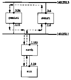
Recall in Figure 4.6 that we explained how proxy ARP is used by the router netb to make it appear as though sun was directly connected to the Ethernet 140.252.1. We've also omitted the modems on the SLIP link between sun and netb, since they're not relevant to this discussion.
In Figure 25.29 we show the path of the Telnet data using dashed arrows, when the address 140.252.3.54 is specified. How do we know that the return packets go directly from gemini to netb, and don't go back the way they came? We use our version of traceroute with loose source routing from Section 8.5:
sun % traceroute -g 140.252.3.54 sun
traceroute to sun (140.252.13.33), 30 hops max, 40 byte packets
1 netb (140.252.1.183) 244 ms 256 ms 234 ms
2 * * *
3 gemini (140.252.3.54) 285 ms 227 ms 234 ms
4 netb (140.252.1.183) 263 ms 259 ms 294 ms
5 sun (140.252.13.33) 534 ms 498 ms 504 ms
When we specify loose source routing, the router swnrt never responds. If we look at the earlier output from traceroute, without source routing, we see that swnrt is indeed the second hop. The reason for the timeouts must be that the router does not generate the ICMP time exceeded errors when the datagram specifies loose source routing. What we are looking for in this traceroute output is that the return path from gemini (TTLs 3,4, and 5) goes directly to netb, and not through the router swnrt.
The question that we need SNMP to answer is what does the routing table entry on netb look like for the destination network 140.252.3? It is netb that sends the packets to swnrt and not directly to gemini. We use the get command to fetch the value of the next-hop router for this destination:
sun % snmpi -a netb -c
secret get ipRouteNextHop.140.252.3.0
ipRouteNextHop.l40.252.3.0=140.252.1.6
This routing table entry tells netb to send the packets to swnrt, which is what we see happen.
Why does gemini send the packets directly back through netb? Because on gemini the destination address of the return packets is 140.252.1.29, and that network (140.252.1) is a directly connected interface.
What we're seeing in this example is a policy routing
decision. The default route to network 140.252.3 is through the
router swnrt because gemini
is intended to be a multihomed host, not a router. This is an
example of a multihomed host that does not want to be a router.
25.10 Traps
All the examples we've looked at so far in this chapter have been from the manager to the agent. As shown in Figure 25.1, it's also possible for the agent to send a trap to the manager, to indicate that something has happened on the agent that the manager might want to know about. Traps are sent to UDP port 162 on the manager.
In Figure 25.2 we showed the format of the trap PDU. We'll go through all the fields in this message when we look at some tcpdump output below.
Six specific traps are defined, with a seventh one allowing a vendor to implement an enterprise-specific trap. Figure 25.30 describes the values for the trap type in the trap message (Figure 25.2).
type | ||
| coldStart | Agent is initializing itself. | |
| warmStart | Agent is reinitializing itself. | |
| linkDown | An interface has changed from the up to the down state (Figure 25.18). The first variable in the message identifies the interface. | |
| linkUp | An interface has changed from the down to the up state (Figure 25.18). The first variable in the message identifies the interface. | |
| authenticationFailure | A message was received from an SNMP manager with an invalid community. | |
| egpNeighborLoss | An EGP peer has changed to the down state. The first variable in the messages contains the IP address of the peer. | |
| enterpriseSpecific | Look in the specific code field for information on the trap. |
We can see some traps using tcpdump. We'll start the SNMP agent on the system sun and see it generate a coldStart trap. (We tell the agent to send traps to the host bsdi. Although we're not running a manager on bsdi to handle the traps, we can run tcpdump and see what packets get generated. Recall from Figure 25.1 that a trap is sent from the agent to the manager, but there is no acknowledgment sent by the manager, so we don't need a manager to handle the traps.) We then send a request using the snmpi program, but with an invalid community name. This should generate an authenticationFailure trap. Figure 25.31 shows the output.
| 1 | 0.0 | sun.snmp > bsdi.snmp-trap: C=traps Trap (28) E:unix.1.2.5 [140.252.13.33] coldStart 20 |
| 2 | 18.86 (18.86) | sun.snmp > bsdi.snmp-trap: C=traps Trap (29)
E:unix.1.2.5 [140.252.13.33] authenticationFailure 1907 |
First we notice that both UDP datagrams are from the SNMP agent (port 161, printed as the name snmp) with a destination port of 162 (printed as the name snmp-trap).
The notation C=traps is the community name of the trap message. This is a configuration option with the ISODE SNMP agent being used.
The next notation. Trap(28) in line 1 and Trap(29) in line 2 is the PDU type and length.
The next field of output for both lines is E:unix.1.2.5. This is the enterprise: the agent's sysObjectID. It falls under the 1.3.6.1.4.1 node of the tree in Figure 25.6 (iso.org.dod.internet.private.enterprises), so this agent's object identifier is 1.3.6.1.4.1.4.1.2.5. Its abbreviated name is unix.agents.fourBSD-isode.5. The final number (5) is the version number of this release of the ISODE agent. This enterprise value identifies the agent software generating the trap.
The next field output by tcpdump is the IP address of the agent (140.252.13.33).
The trap type is printed as coldStart on line 1, and authenticationFailure on line 2. These correspond to trap type values of 0 and 4, respectively (Figure 25.30). Since these are not enterprise-specific traps, the specific code must be 0, and is not printed.
Next comes the timestamp field, printed as 20 and 1907. This is a TimeTicks value, representing the number of hundredths of a second since the agent initialized. In the case of the cold start trap, the trap was generated 200 ms after the agent was initialized. The tcpdump output indicates that the second trap occurred 18.86 seconds after the first one, which corresponds to the printed value of 1907 hundredths of a second, minus 200 ms.
Figure 25.2 indicates that a trap message can contain
interesting variables that the agents wants to send to the manager,
but there aren't any in our examples.
25.11 ASN.1 and BER
The formal specification of SNMP uses Abstract Syntax Notation 1 (ASN.1) and the actual encoding of the bits in the SNMP messages (Figure 25.2) uses the corresponding Basic Encoding Rules (BER). Unlike most texts that describe SNMP, we have purposely left a discussion of ASN.1 and BER until the end. When they're discussed first, it can confuse the reader and obfuscate the real purpose of SNMP-network management. In this section we only give an overview of these two topics. Chapter 8 of [Rose 1990] covers ASN.1 and BER in detail.
ASN.1 is a formal language for describing data and the properties of the data. It says nothing about how the data is stored or encoded. All the fields in the MIB and the SNMP messages are described using ASN.1. For example, the ASN.1 definition of the data type IpAddress from the SMI looks like:
| IpAddress ::= | ||
| [APPLICATION 0] | -- in network-byte order | |
| IMPLICIT OCTET STRING (SIZE (4)) |
Similarly, from the MIB we find the following definition of a simple variable:
| udpNoPorts OBJECT-TYPE | ||
| SYNTAX Counter | ||
| ACCESS read-only | ||
| STATUS mandatory | ||
| DESCRIPTION | ||
| "The total number of received UDP datagrams for which there was no application at the destination port." | ||
| :: = { udp 2 } | ||
The definition of tables using SEQUENCE and SEQUENCE OF is more complex.
Given these ASN.1 definitions, there are many ways to encode the data into a stream of bits for transmission. SNMP uses BER. The representation of a small integer, such as 64, requires 3 bytes using BER. One byte says the value is an integer, the next byte says how many bytes are used to store the integer (1), and the final byte contains the binary value.
Fortunately the details of ASN.1 and BER are only
important to implementors of SNMP. They are not fundamental to
the understanding and use of network management.
25.12 SNMP Version 2
During 1993 11 RFCs were published defining revisions to SNMP The first of these, RFC 1441 [Case et al. 1993], provides an introduction to SNMP Version 2 (SNMPv2). Two books also describe SNMPv2 [Stallings 1993; Rose 1994]. Two publicly available implementations already exist (see Appendix B.3 of [Rose 1994]), but vendor implementations probably won't be widely available until 1994.
In this section we describe the major differences from SNMPv1 to SNMPv2.
As vendors start to provide SNMPv2-capable agents,
management stations will also appear that can handle both. [Routhier
1993] describes extending an implementation of SNMPv1 to support
SNMPv2.
25.13 Summary
SNMP is a simple request-reply protocol between an SNMP manager and an SNMP agent. The management information base (MIB) defines the variables that are maintained by the agent, for the manager to query or set. Only a limited number of data types are used to define these variables.
All the variables are identified by object identifiers, a hierarchical naming scheme consisting of long strings of numbers that are normally abbreviated into a simple name, for human readability. A specific instance of a variable is identified by appending an instance to the object identifier.
Many SNMP variables are contained in tables, with a fixed number of columns, but a variable number of rows. Fundamental to SNMP is the identification scheme used to identify each row in a table (when we don't know how many rows are in the table), and the lexicographic ordering (column-row order). The end result, SNMP's get-next operator, is basic to any SNMP manager.
We then described the following groups of SNMP variables: system, interface, address translation, IP, ICMP, TCP, and UDP. This was followed by two examples, one to determine the MTU of an interface, and the other to look at the routing table of a router.
We completed the chapter by looking at SNMP traps, a way for the agent to notify the manager that something significant has occurred, and a brief mention of ASN.1 and BER. These latter two topics are probably the most confusing aspects of SNMP, but fortunately their details are needed only by implementors.
25.1 We said that using two different ports (161 and 162) allows a system to run both a manager and agent. What would happen if the same port number were used for both?
25.2 How would you list an entire routing table using get-next?